If two resistors with resistances r1 and r2 – When two resistors with resistances R1 and R2 are connected in series or parallel, the total resistance of the circuit changes. Understanding the concepts of series and parallel circuits is crucial for analyzing and designing electrical circuits.
This comprehensive guide explores the behavior of resistors in series and parallel configurations, providing insights into the calculation of total resistance and the distribution of voltage and current within the circuits.
Electrical Resistance

Electrical resistance is a property of materials that impedes the flow of electric current. It is measured in ohms (Ω). Materials with high resistance, such as rubber and wood, allow little current to flow through them. Materials with low resistance, such as metals, allow current to flow easily.
The resistance of a conductor is affected by several factors, including its length, cross-sectional area, and temperature.
Resistors in Series, If two resistors with resistances r1 and r2
Resistors in series are connected one after the other, so the current flows through each resistor in turn. The total resistance of resistors in series is the sum of the individual resistances.
| Resistor 1 | Resistor 2 | Resistor 3 | Total Resistance |
|---|---|---|---|
| 10 Ω | 20 Ω | 30 Ω | 60 Ω |
- Calculate the total resistance by adding the individual resistances.
- For example, in the table above, the total resistance is 10 Ω + 20 Ω + 30 Ω = 60 Ω.
Resistors in Parallel
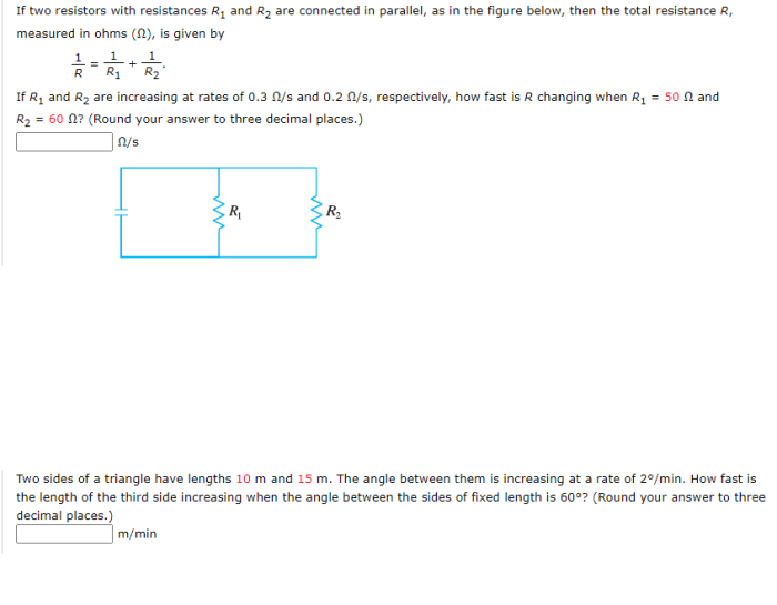
Resistors in parallel are connected side by side, so the current can flow through any of the resistors. The total resistance of resistors in parallel is less than the smallest individual resistance.
| Resistor 1 | Resistor 2 | Resistor 3 | Total Resistance |
|---|---|---|---|
| 10 Ω | 20 Ω | 30 Ω | 6.67 Ω |
- Calculate the total resistance using the formula: 1/Total Resistance = 1/Resistance 1 + 1/Resistance 2 + 1/Resistance 3 + …
- For example, in the table above, the total resistance is 1/(1/10 Ω + 1/20 Ω + 1/30 Ω) = 6.67 Ω.
Voltage and Current in Series and Parallel Circuits
In a series circuit, the voltage is the same across each resistor, and the current is the same through each resistor. In a parallel circuit, the voltage is the same across each resistor, and the current is different through each resistor.
Experiment to Measure Voltage and Current in a Series Circuit:
- Connect a battery, a voltmeter, and an ammeter in series.
- Measure the voltage across the battery and the current through the circuit.
- Connect a resistor in series with the battery, voltmeter, and ammeter.
- Measure the voltage across the resistor and the current through the circuit.
- Repeat steps 3 and 4 with different resistors.
Experiment to Measure Voltage and Current in a Parallel Circuit:
- Connect a battery, a voltmeter, and an ammeter in parallel.
- Measure the voltage across the battery and the current through the circuit.
- Connect a resistor in parallel with the battery, voltmeter, and ammeter.
- Measure the voltage across the resistor and the current through the resistor.
- Repeat steps 3 and 4 with different resistors.
Applications of Resistors
Resistors are used in a wide variety of applications, including:
- Current limiting:Resistors can be used to limit the current flow in a circuit.
- Voltage division:Resistors can be used to divide the voltage in a circuit.
- Signal conditioning:Resistors can be used to filter out noise and unwanted signals.
- Temperature sensing:Resistors can be used to sense temperature changes.
Advantages of Using Resistors in Series:
- The total resistance of resistors in series is greater than the resistance of any individual resistor.
- Resistors in series can be used to limit the current flow in a circuit.
Disadvantages of Using Resistors in Series:
- The voltage drop across each resistor is the same.
- If one resistor fails, the entire circuit will stop working.
Advantages of Using Resistors in Parallel:
- The total resistance of resistors in parallel is less than the resistance of any individual resistor.
- Resistors in parallel can be used to increase the current flow in a circuit.
Disadvantages of Using Resistors in Parallel:
- The voltage drop across each resistor is the same.
- If one resistor fails, the other resistors will continue to function.
Example of a Circuit that Uses Resistors in Series and Parallel:
A voltage divider circuit uses resistors in series and parallel to divide the voltage in a circuit. This type of circuit is often used to power electronic devices.
Commonly Asked Questions: If Two Resistors With Resistances R1 And R2
What is the difference between series and parallel circuits?
In a series circuit, the resistors are connected one after the other, forming a single path for the current to flow. In a parallel circuit, the resistors are connected side by side, providing multiple paths for the current to flow.
How do you calculate the total resistance of resistors in series?
To calculate the total resistance of resistors in series, simply add their individual resistances. For example, if two resistors have resistances of 10 ohms and 15 ohms, the total resistance is 25 ohms.
How do you calculate the total resistance of resistors in parallel?
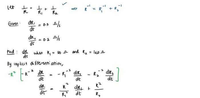
To calculate the total resistance of resistors in parallel, use the following formula: 1/Total Resistance = 1/R1 + 1/R2 + … 1/Rn, where R1, R2, …, Rn are the resistances of the individual resistors.


